The following subsections will guide you through the installation and general setup of your Robotiq Hand-E Gripper.
Warning
Before installing:
Warning
When installing:
Standard upon delivery
Info
Please refer to the Spare Parts, Kits and Accessories section for a list of available couplings.
Caution
The following are not included in the standard delivery:
Info
When bought as a kit, the Hand-E Gripper will come in a package with the appropriate coupling, fingers/fingertips and cabling. Please refer to the Spare Parts, Kits and Accessories section.
The following tools are required to install the Hand-E Gripper:
Optional tools if installing fingertip/holder kits: HND-FIN-ALU-KIT, HND-TIP-RUB-KIT, HND-TIP-VGR-KIT, HND-TIP-HLD-KIT
The following parts are required for setup :
The Gripper needs to be supplied by a DC voltage source. This power supply is not included with the Gripper. Required power supply must match the Robotiq device. The following table shows the specifications with regards to the power supply required to operate the Gripper and the optional Robotiq Controller.
|
SPECIFICATION |
VALUE |
|---|---|
|
Output voltage |
24 V DC ±10% |
|
Output current |
1 A |
|
Overcurrent |
Recommended power supply with internal protection, otherwise fusing is required. 2 A fuse at 25°C [77°F]1 |
Table 3-1: Hand-E power supply requirements.
1 Suggested fuse is a: Phoenix Contact # 0916605 2 A thermal, use AWG #20 wiring.
Warning
If your power supply could exceed the specified regulation, over-voltage protection is required.
Robotiq recommends the use of the following power supplies:
Tip
Optional Robotiq Universal Controller can use the same power supply.
|
CONDITION |
VALUE |
|---|---|
|
Minimum storage/transit temperature |
-30°C [-22°F] |
|
Maximum storage/transit temperature |
60°C [140°F] |
|
Minimum operating temperature |
-10°C [14°F] |
|
Maximum operating temperature |
50°C [122°F] |
|
Humidity (non-condensing) |
20-80% RH |
|
Vibration |
< 0.5G |
|
Other |
IP 67 |
Table 3-2: Environmental and operating conditions of the Hand-E Gripper.
The figures below list the material and tools needed to mount fingers or fingertips/holders onto the racks of the Hand-E Gripper.
Fig. 3-1: Mounting the fingers on the racks

Fig. 3-2: Mounting fingertips on holders (and then on the racks)
Use a coupling to attach the Gripper to the robot. Be sure to use the appropriate coupling for your robot model. If there is no coupling for your robot, you can process a blank coupling or Robotiq can create a custom version for you. Some couplings may require an additional adapter plate. To create your own coupling and/or adapter plate you can refer to the Couplings section. To see the details of the available couplings and adapter plates, please refer to the Spare Parts, Kits and Accessories section.
Here are the steps to follow to mount the Gripper to your robot (see figure below). Note that all screws must be locked in place using medium strength threadlocker.

Fig. 3-3: Installing the Gripper to a robot using an adapter plate and a coupling.
When installing multiple grippers on one robot, every gripper must have its own coupling.

Fig. 3-4: Dual Hand-E Gripper Configuration
Power and communication are established with the Hand-E Gripper via a single device cable. The device cable provides a 24V power supply to the Gripper and enables serial RS485 communication to the robot controller.
Info
RS485 signals (485+, 485- and 485 GND) are isolated from the main 24V power supply. GND can be connected to any other ground reference as long as the voltage potential between the grounds does not exceed 250V. Grounding reference is at the user's discretion.
The Gripper interfaces with its coupling via a 10-spring pin connector located on its outer surface.
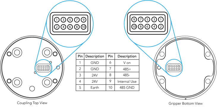
Info
The coupling used in the figure above is used for reference only and corresponds to bolt pattern ISO 9409-1-50-4-M6.
An optional Robotiq Universal Controller may be used between the Gripper and the network/robot controller if fieldbus communication is required.
If a Robotiq Universal Controller is used, please refer to the instruction manual of the Robotiq Universal Controller. The figure below represents the wiring scheme of the Hand-E Gripper with device cable, power supply, fuse (refer to the Required Tools and Equipment section) and grounding.

Fig. 3-5: Robotiq Hand-E with pigtail cable and device cable wiring scheme.
Caution
Use proper cabling management. Make sure to leave enough slack in the cabling to allow movement of the Gripper along all axes without pulling out the connectors. Always protect the controller side (robot side) connector of the cable with a strain relief cable clamp.
The figure below illustrates the Hand-E Gripper pigtail connector from the coupling (GRP-CPL-062 or AGC‑CPL‑XXX-002), the device cable on the robot side (CBL‑COM‑2065‑10-HF) and their associated pinout.
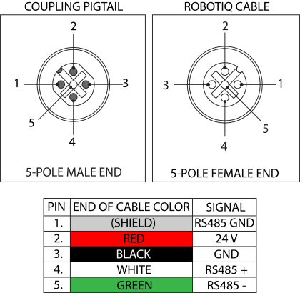
Table 3-3: Pinout of the Hand-E Gripper pigtail and device cable.
If additional cables are used, suggested cable specifications are as follows:
Power supply, fusing
RS485 signal
Prior to any software installation on Universal Robots, connect the white, blue and bare wires to the Robotiq RS-485 signal converter (ACC-ADT-RS485-USB) as shown in the figure below. Also connect the red (24V) and black (0V) wires in the terminal blocks of the robot controller.
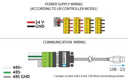
Fig. 3-6: Hand-E Gripper wiring to Universal Robots controller.
It is possible to connect and control up to four grippers on the same UR robot. Only one USB to RS485 converter (ACC- ADT-USB-RS485) must be used. Use M12 splitters (ACC-SPLIT-M12-2:1) to connect all the grippers pigtails to one 10m cable
(CBL-COM-2065-10-HF) that connects to the RS485 to RS232 converter.
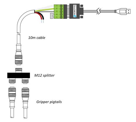
Fig. 3-7: Multiple grippers wiring.
Once installed and properly secured, your Robotiq Hand-E Gripper should be tested with the Robotiq User Interface test software using the provided USB converter. To do so :
Use the provided RS-485 to USB converter ACC-ADT-USB-RS485 (refer to the figure below) to plug into a PC with the Robotiq User Interface installed.
Caution
The Activate command will initiate movement of the Gripper for the auto-calibration procedure. Do not interfere with the Gripper. Be sure you have met robot safety measures.

Fig. 3-8: RS-485 to USB converter ACC-ADT-USB-RS485 pinout.
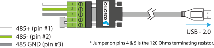
Fig. 3-9: Wiring possibilities of the USB to RS-485 converter.
Tip
With the RUI controlling the Gripper, you can go to the "view" menu to see input and output register values to further your understanding on how to command the Gripper. You can also test gripping your parts with various speed and force settings. Please refer to the Control section for details.
The table below shows which Robotiq software to use with your Universal Robots controller. If you are using a CB3 or CB3.1 controller, it is recommended to use the Hand-E Gripper URCaps Package.
|
Robotiq Software |
Controller CB1 |
Controller CB2 |
Controller CB3 |
Controller CB3.1 |
e-Series Controller |
|---|---|---|---|---|---|
|
Driver Package |
Incompatible |
Compatible |
Compatible |
Compatible |
Incompatible |
|
Robotiq Grippers URCap Package 1.2.1 and earlier versions |
Incompatible |
Incompatible |
Compatible |
Compatible |
Incompatible |
|
Robotiq Grippers URCap Package 1.3.0 |
Incompatible |
Incompatible |
Incompatible |
Compatible |
Incompatible |
|
Robotiq Grippers URCap Package 1.3.1 and later versions |
Incompatible |
Incompatible |
Incompatible |
Compatible |
Compatible |
Table 3-4: Compatibility between Robotiq software and robot controller
Refer to the URCap Package section for the installation of the UR software package for Hand-E.
Caution
The robot's PolyScope version must be 3.5 or later in order to install the URCap.
Caution
Prior to use over Universal Robots, adjust the payload and the center of gravity in the Installation tab (refer to the Mechanical specifications section).
Caution
Please refer to the Installing URCap Package section to configure the grippers properly before controlling and programming them.
Robotiq provides you with a Universal Robots URCap package that enables direct serial communication to your UR controller.
Info
To get the URCap package for your UR controller, browse to Hand-E's support product page.
Make sure the Hand-E Gripper is properly mounted to the robot arm. Refer to the Mechanical Installation section for detailed information on the mechanical installation. Before proceeding with the installation of the URCap package, make sure your Universal Robots controller is compatible with the package (refer to the Installation for Universal Robots section).
Caution
The robot's PolyScope version must be 3.5 or later in order to install the URCap.
The Gripper’s URCap package contains:
Tip
For other robots, where no driver package is available, we recommend the use of the Robotiq Universal Controller which allows fieldbus communication. Available communication protocols with this Universal Controller are:
For details on controlling the Gripper, please refer to the Control section.
Info
Please refer to the Control over Universal Robots with URCaps section for detailed information on how to program using the URCap package.
Make sure the Hand-E Gripper is properly mounted to the robot arm. Refer to the Mechanical Installation section for detailed information on the mechanical installation. Before proceeding with the installation of the URCap package, make sure your Universal Robots controller is compatible with the package (refer to the Installation for Universal Robots section).
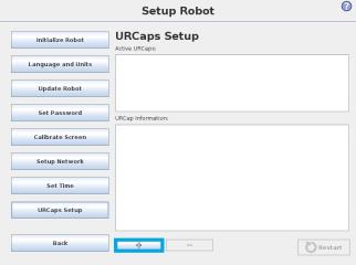
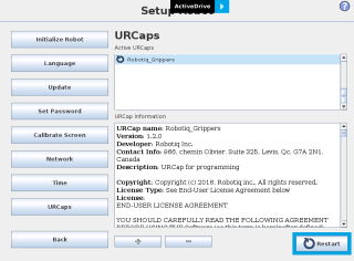
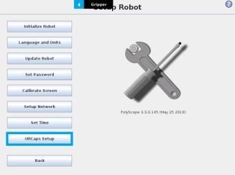
Follow this procedure to install the Hand-E Gripper URCap package:
|
|
|
Tip
If you wish to know what version of PolyScope you are using, go to the PolyScope home page and tap the About button. A window containing the Universal Robots software version will pop up.
|
|
|
|
|
|
|
|
|
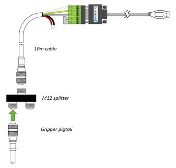
It is possible to connect and control up to four grippers on the same UR robot.
Only one USB to RS485 converter (ACC- ADT-USB-RS485) must be used. Use M12 splitters (ACC-SPLIT-M12-2:1) to connect all the grippers pigtails to one 10m cable (CBL-COM-2065-10-HF) that connects to the USB to RS485 converter.

Fig. 3-10: Wiring for multiple grippers.
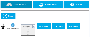
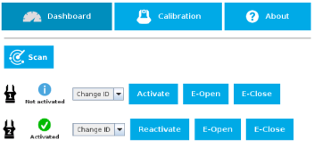
When installing multiple grippers on one UR robot, their gripper ID must be set properly. To do so, perform the following steps for each Gripper.
|
|
|
|
|
|
|
|
Caution Make sure all grippers have different IDs. With their factory settings, all grippers have Gripper ID set to 1. If you have more than one gripper connected with the same ID, communication issues will arise. |
|
|
|
If you wish to uninstall the Hand-E Gripper URCap, follow this procedure:
|
|
|
|
|
|
|
|
|
END-USER LICENSE AGREEMENT
YOU SHOULD CAREFULLY READ THE FOLLOWING AGREEMENT BEFORE USING THE Software (as this term is hereinafter defined). Using the Software indicates your acceptance of the agreement. If you do not agree with it, you are not authorized to use the Software.
IMPORTANT-READ CAREFULLY: This End-User License Agreement (the “Agreement”) is a legal agreement between you and the Licensor (as this term is hereinafter defined), the licensor of the Software. This Agreement covers the Software. The Software includes any “on-line” or electronic documentation and all modifications and upgrades related thereto. By installing, or otherwise using the Software, you agree to be bound by the terms of this Agreement. If you do not agree to the terms of this Agreement, the Licensor cannot and does not license the Software to you. In such event, you must not use or install the Software.